 Quick Navigation
 All projects
  Hardware
 Links
Links Top projects
Alan numitron clock
Clapclap 2313/1386
SNES Pi Webserver
USB Volume/USB toys
Smokey amp
Laser cutter
WordClock
ardReveil v3
SNES Arcade cabinet
Game boy projects
cameleon
Home Presence Detector
 GitHub
AlanFromJapan
 Contact me
 Who's Alan?
Akizukidenshi
Elec-lab
Rand Nerd Tut
EEVblog
SpritesMods
AvrFreaks
Gameboy Dev
FLOZz' blog
Switch-science
Sparkfun
Suzusho
Datasheet Lib
Reddit Elec
Ermicro
Carnet du maker (fr)
aquarium lights
Last update: Tue Feb 17 20:52:01 2026
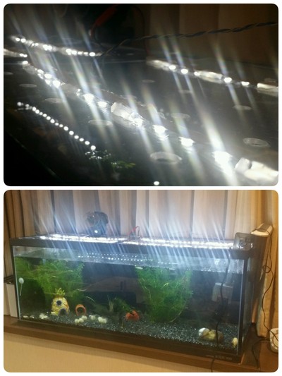 Basic aquarium lights based on 555, MOSFET and leds.
Presentation
Principle
I was a shameless sinner who made aquarium lights with a resistor to limit the current and a boost converter. I have no excuse. And when the powers of the aquarium decided that water spash would finish eating the copper of my connector, I understood the message from above (well, below in that case since the water is below the leds): make it right.So I'll use a proper power source, with led strip (still) and PWM modulation (which means 555). Basic circuit, but the best answer to a basic need.
Points of interrest
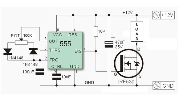
555 and PWM made simple: honnestly I didn't find aywhere on the net any simpler PWM with 555 circuit. 2 resistor, 1 cap, 1 diode and you get a range from 1% to 99% duty PWM, this is the simplest 555 PWM circuit I could find. Just what you need in most cases. Other circuits have more parts without being that much more complex to be honnest. Let's use this one and see.The idea is to set the simplest possible astable 555 oscillator. One other very similar circuit is here, with an online calculator.
In a nutshell, the key ideas are (from above site):
Implementation
Bill of materials
Settings
With a measured duty cycle of 50%, we're at about 5-7kHz (forgot exactly), and with a bit less than 2 meters of white led strips we have a comsumption of 0.47A at 12V (says my power supply). It's bright enough, and after a couple hours of continuous running, the "hottest" component was the 555 that went lukewarm. All the rest and especially the MOSFET staid at room temperature.Schematics
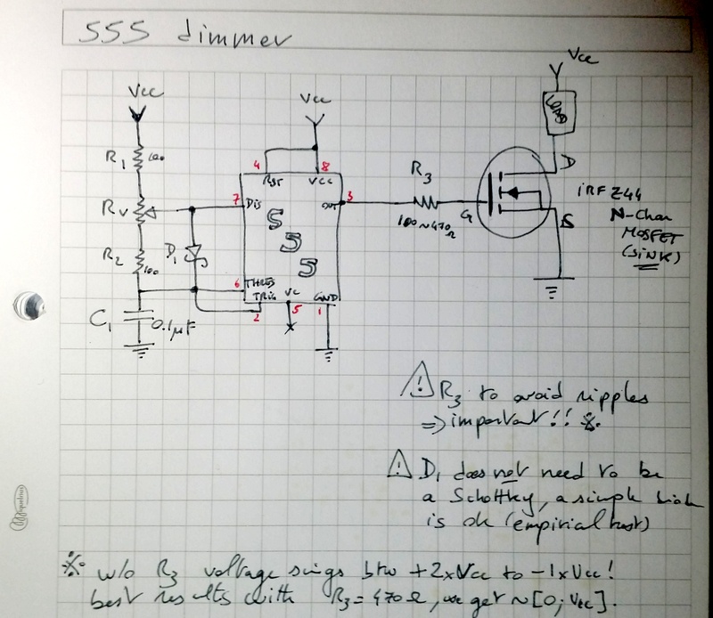
That's what I made↑
Nota bene:
Source code
None in this case, there's no mCU.Pictures
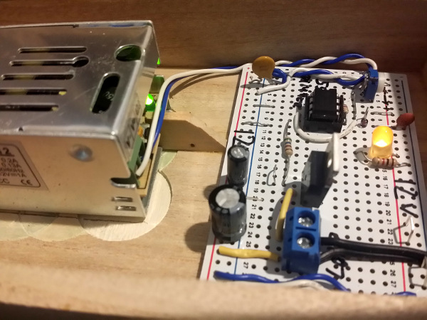
The circuit on the simple PCB in shape of breadboards. Love these for simple circuits.
Links
Helpful sources
Inspiration
Nota Bene: if you follow this link you'll find a simpler version with only 2 resistor and 1 cap BUT the minimum duty cycle I can get without the Schotky diode is 30%-ish (100 ohm/100ohm/0.1uF). With a simple Schotky diode, you get a 1%-90% duty easily.
electrogeek.tokyo ~ Formerly known as Kalshagar.wikispaces.com and electrogeek.cc (AlanFromJapan [2009 - 2026])